Air brake chalk board What is he talking about??? Part 2 in Tales of the Jointed Track
- July 3, 2015, 11:22 a.m.
- |
- Public
Remember my last statement in Part 1? Air pressure opposing air pressure. There are many components in the braking system. Let’s simplify this, and I did this with my fireman. Lets make this in your mind, like water flowing, through a hose, or a like a phone call over the “land-line”.
The Automatic Brake Valve is what the engineer uses to apply, release and recharge the brake pipe and the cars. That Automatic brake Valve is the SIGNAL SENDER. (Water you turn on the outside faucet.. Land line or Cell, you initiate the call)
The train-line or “brake pipe” runs through the length of the entire train. Regardless, of just lite power, or a 150 cars, or more. The locomotives and cars have a physical brake pipe. The connections between each is an air hose. This is a heavy reinforced rubber hose, with a screw on connection to the angle cock and a glad hand that allows it to fasten to another. That’s the hose you see below the couplers, with a slight or pronounced loop. This is the SIGNAL RE-LAYER. (Water in the hose .. Land line the telephone wires to route and connect your call ..Cell Phone the Cell towers.)
For those that live around, or routinely cross main lines, you can see on grain hoppers and tank cars, you can spot that piped train line, on the side or offset underneath on tank cars.
There is a piped union called a brake pipe branch pipe. That is what now connects the air from the brake pipe to the individual cars. This air heads into the control valves on each car. That’s why, the brake pipe charges first, then air goes into the branch pipe, to start the charging of the cars in the train. The control valves are your SIGNAL RECEIVER. (Water your sprinkler heads or sprinkler. Land line or Cell the call reaches your intended number and is answered).
Control valves Locomotives and freight cars;
The control valve, this is what makes that brake application, or that release work.
There are three portions, The pipe bracket, the service portion and the emergency portion. The service and emergency portions bolt to the pipe bracket. The branch pipe is on the back of the pipe bracket. So here is the air flow, into the control valve. Who charges first? The Auxiliary or the Emergency reservoir on the cars?. The emergency reservoir will charge first, then the auxiliary reservoir.
Okay, yer thinking, hmmm geez how do they ever get out of the terminal. A 80 car freight, at origination, will charge within 40 minutes at a 70 F temperature. Another topic, but air is being forced through the brake pipe. Air hates being compressed, no it did not write me. Physics, states that, and like weather, compression generates heat. There are inter-coolers that help dissipate heat.
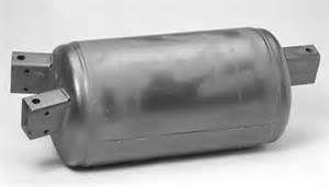
A fabricated newer style Auxiliary and emergency reservoir a newer style of auxiliary and emergency air reservoirs for freight cars. Some are two separate halves and are bolted together. The larger of the bolted half will be your emergency reservoir.
The diaphragm in the service portion will re-align, after the Emergency reservoir is charged. The air flow to the Auxiliary reservoir will charge that volume.
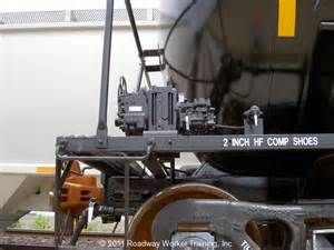
A tank car showing the air brake equipment. Looking at the car starting from the left, That is the emergency portion. The center is the pipe bracket, where the air equipment and associated piping to the reservoirs and brake cylinder and retainer valve piping is attached. The right is Service portion, that reacts to the reducing or increase in brake pipe pressure, therefore applying the brakes or releasing them and redirecting air back into the auxiliary reservoir to charge it for the next application.
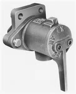
To the right of that is the retaining valve. The hissing noise you hear, when the car and/or train is releasing the air, is air coming from the brake cylinder through the control valve and out the retainer. The handle is pointed down it is in the release mode. click up one position left High Pressure, click up one more, Low Pressure, click up to the last position. Slow direct.
*A Freight car retaining valve. These are used on mountain grades only and as needed or required by Division operating rule. This is a Three position retainer, some have a four position with LP (low pressure setting). EX is a direct exhaust of the brake cylinder for a full release. HP (high Pressure) will restrict the exhaust of the Brake cylinder the will hold 20 psi of brake cylinder pressure. LP (Low Pressure) will restrict the exhaust of the Brake cylinder the will hold 10 psi of brake cylinder pressure. SD (Slow Direct) This will restrict the exhaust of the brake cylinder pressure at a controlled rate to provide a blowdown time around 86 to 90 seconds and then continues till the brake cylinder air pressure is vented to the atmosphere. *
We are ready for the air test. A call is made to set the air. The brake valve is moved to the FULL SERVICE position. Or off the Equalization reservoir gauge, set from 90 lbs to the 70 lbs. The train line or brake pipe will correspond at a service rate. The rear car of the train MUST be within 15 lbs of the feed valve setting, or a minimum of 75 lbs on the gauge or ETD. Most trains, will be around 80-to 85 lbs at the terminal, and the Carman will call for the set.
The air is exhausting out the of the brake valve. The reduction is being made, and several things are happening. Air that is exhausting will come forward from the entire length of the train, through the automatic brake valve. As the reduction is coming to an end, the exhaust starts to slow, and the “cutoff” begins as the desired application is reached. The freight cars are reacting as well, some are setting up or have set, some are just sensing the reduction, some are still waiting for that reduction. Lets focus on a freight car, lets say 37 cars back. The service portion of the control valve has sensed the drop in brake pipe pressure from a 90 lbs pipe to a 70 lbs condition. The diaphragms and springs are realigning the air passages and ports from a charging state, to allowing air to flow into the brake cylinder. If you are near a train that is setting the air, and not going by you, you may hear the repeating “gush clicking” near the control valve. That is the diaphragms, springs and spool valving reaction to the change of pressure. You also may hear the piston coming out of the brake valve, and moving the rods and levers, forcing the brake shoes to the wheel tread.
The Car man has made the physical inspection of the freight cars, and is asking for a release. The engineer has timed the leakage, or has watched the set with the aid of the flow meter, that should be at or close to zero.
The brake valve handle is moved to the release position and the Car man will ride the release on one side and watch the other side as the train is cleared to leave town. The brake pipe is now increasing in pressure, to the feed valve setting at 90 lbs. This is triggering a release. The control valve is now aligning ports and the Auxiliary reservoir is beginning to charge, as well as aligning ports to allow the brake cylinder to release its air. With the newer and more modern air braking, the emergency reservoir will spill a small amount of air into the brake pipe to allow that to pressurize faster, to allow the cars to begin recharging faster. The ports are also aligned to allow that brake cylinder air through the retaining valve. As the brake cylinder air pressure is lessening, there is a spring inside that brake cylinder that is riding the piston between the boot and the end of the cylinder. The spring pressure is now becoming greater than the air pressure, forcing the air out of the brake cylinder.
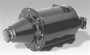
a car body mounted air brake cylinder for freight cars.
Part 3 will explain the graduation on the engineers automatic brake valves and the emergency application. How the emergency and service portions react in conjunction with each other.
Last updated July 07, 2015


ChallengerSeven ⋅ July 03, 2015
Great entry. You're confirming what I know - or think I know! :-) - and adding new info (emergency res. air into the brake pipe for faster recharging.)
Awaiting Part 3!
MageB ⋅ July 06, 2015
I feel totally uninformed.
My brain is a blank..............reading on.............
Brakeshoe Bob MageB ⋅ July 06, 2015
Just follow no test Just trying to explain how it all works
I had a blank stare on this when I hired out. It clicked I tried to make it more understandable to the people i trained...
My best as always